
Introduction
Picture a robot arm reaching into a bin of randomly stacked castings. Every part sits at a different angle, some overlapping, some catching glare off a machined surface.
A traditional 2D camera sees a flat image. It has no way to tell which part is closest, which way it's facing, or whether the gripper will collide with the bin wall.
This is the wall manufacturers hit as production lines demand more flexibility: mixed part types, reflective surfaces, and unstructured environments that 2D vision was never built to handle. That gap is driving rapid adoption of 3D machine vision.
This article breaks down what 3D machine vision actually is, how it captures depth, how it stacks up against 2D vision, where it shows up in robotic automation, what it costs, and how to pick the right system for your application.
Key Takeaways
- 3D vision captures X, Y, and Z data, giving robots real depth perception instead of a flat picture
- Stereo, Time-of-Flight, and structured light/laser triangulation are the three primary depth-capture methods
- 3D-camera revenue is growing at a 13% CAGR through 2028, more than double the overall machine-vision market
- Bin picking, machine tending, and dispensing validation are the most common industrial 3D vision applications
- Matching hardware to your application and robot programming matters more than chasing camera specs alone
What Is 3D Machine Vision Technology?
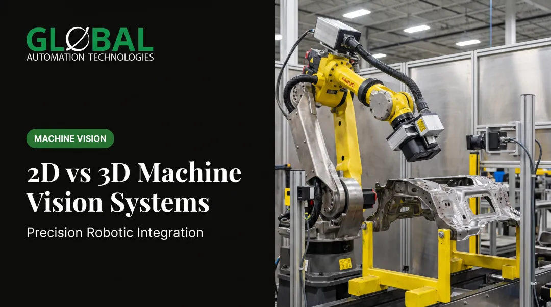
3D machine vision combines cameras or sensors, lighting or projection hardware, and processing software to capture spatial data across three axes (X, Y, and Z). Instead of producing a flat image, the system builds a 3D model or point cloud that lets a machine understand an object's depth, shape, and orientation in space.
That distinction matters for robotics. A 2D system can confirm a label is present. A 3D system can tell a robot exactly where a part sits, which way it's tilted, and how far the gripper needs to travel to reach it.
Core Components of a 3D Vision System
Every industrial 3D vision setup relies on three working parts:
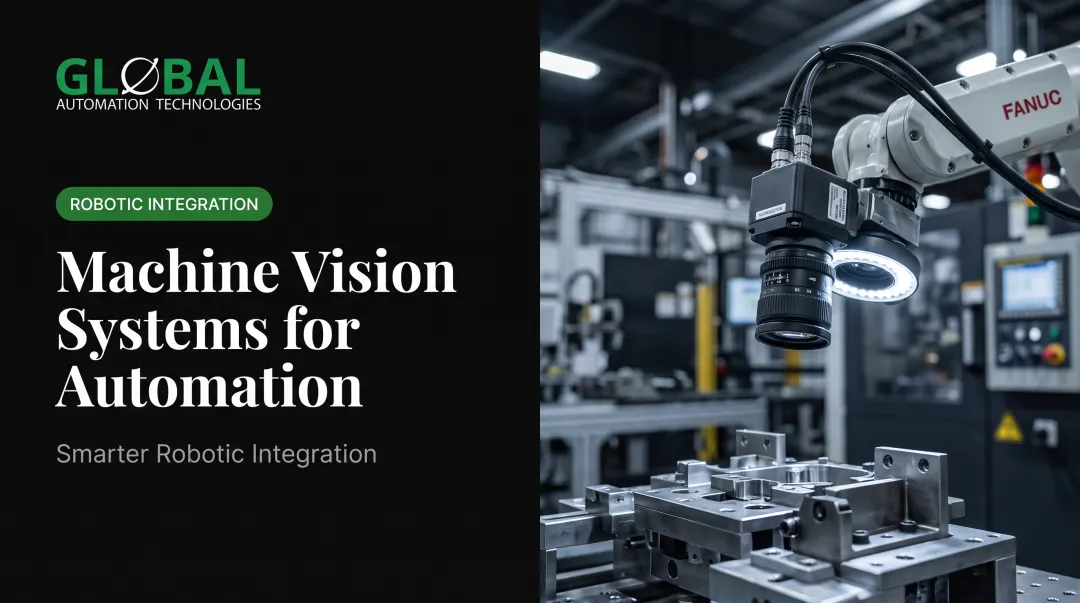
- Cameras and sensors: capture data from multiple angles or use dedicated depth-sensing hardware
- Lighting and projection systems: structured light or IR projectors that keep illumination consistent on shiny, dark, or reflective parts
- Software and algorithms: stitch raw sensor data into a point cloud, recognize objects, and calculate robot guidance coordinates
Without the software layer, raw depth data is just noise. It's the algorithm that turns millions of data points into an actionable position for a robot arm.
How 3D Vision Systems Capture Depth
Manufacturers choose between three main depth-capture approaches:
| Method | How it works | Best fit |
|---|---|---|
| Stereo vision | Two cameras positioned apart calculate depth from disparity, similar to human binocular vision | Snapshot scenes with no camera or object movement |
| Time-of-Flight (ToF) | Measures how long emitted light takes to travel to an object and back | Large fields of view, working distances beyond about 0.5 meters, high-speed capture |
| Structured light / laser triangulation | Projects known light patterns or a laser line and measures how it deforms across the surface | High-precision measurement, profile and seam inspection |
Snapshot methods like stereo and structured light capture the whole scene in one shot but can be less accurate than scanning-based approaches. Scanning laser triangulation requires relative motion between the sensor and part but delivers tighter dimensional accuracy. That is why it shows up so often in weld tracking and profile inspection.

3D vs 2D Vision: What's the Difference?
2D vision captures flat, length-and-width imaging. It's well suited to surface-level tasks: barcode reading, label verification, presence/absence checks. What it can't do is tell you how tall something is, how it's oriented, or where it sits in three-dimensional space.
3D vision adds depth perception to that flat image. That extra dimension is what makes robotic bin picking, volumetric inspection, and complex assembly guidance possible.
Where each technology fits
| Factor | 2D Vision | 3D Vision |
|---|---|---|
| Data captured | Surface appearance only | Depth, volume, geometry |
| Typical use | Barcode reads, label checks, presence/absence | Robotic guidance, volumetric inspection, pose detection |
| Environmental tolerance | Sensitive to lighting changes | Handles reflective and irregular surfaces better with proper illumination |
| Relative cost | Lower | Higher, but justified when depth is required |
The growth numbers back up where the industry is headed. Interact Analysis forecasts 3D-camera revenue growing at a 13% CAGR through 2028, more than double the 6.4% growth rate projected for the total machine-vision market. Manufacturers aren't replacing 2D vision — they're adding 3D capability wherever depth actually changes the outcome.
Practical rule of thumb: use 2D vision for simple, flat inspection tasks. Use 3D vision the moment depth, orientation, or spatial accuracy determines whether a robot succeeds or fails at the task.
How 3D Vision Powers Robotic Automation
Depth data is only valuable once it feeds a robot controller in real time. This is where 3D vision earns its keep on the plant floor.
Bin picking and palletizing. A 3D camera scans a bin of randomly oriented parts, calculates each part's position and orientation, and passes coordinates to the robot. The robot grasps accurately with no manual fixturing, even when parts overlap or shift between cycles.
Machine tending. Vision-guided robots load and unload CNC machines without needing parts pre-positioned on a fixture. Machine tending cells like these often pay back in roughly 12 to 18 months. Gains come from higher spindle utilization and extended runs beyond a single shift, between scheduled maintenance windows.
In-process quality validation. Real-time vision inspection can catch bead or dispensing defects (thin adhesive lines, missed sealant paths, voids in cavity fill) before the part moves downstream. Catching it at the station beats catching it after final assembly, every time.
Precision dispensing and painting. Vision guidance locates and orients parts so robotic painting and dispensing follows the same programmed path every cycle, holding coating consistency shift after shift. That repeatability cuts overspray and material waste versus manual application, while full finish inspection with robotic touch-up happens downstream rather than live in the booth.
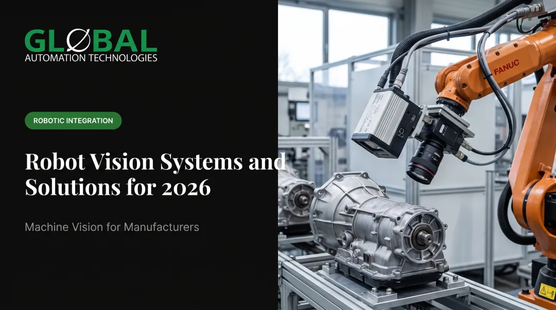
GLOBAL, a top-tier Level 5 FANUC Authorized System Integrator, builds 3D vision directly into full turnkey robotic cells, covering:
- Layout and application analysis
- Robot programming using AI-assisted simulation
- Vision system integration and calibration
- Validation testing before commissioning
- On-site commissioning and startup support
The AI-assisted simulation step matters. Modeling and testing robot programs before the first line of code runs on the floor shortens programming time and cuts down on startup surprises. GLOBAL's cells are built primarily around FANUC robots. Hollow-wrist cable routing, intrinsically safe designs for hazardous spray environments, and process control tight enough for Class A automotive finishes all matter when vision-guided accuracy is non-negotiable.

Industries That Rely on 3D Machine Vision
3D vision adoption tends to cluster wherever geometry, not just appearance, determines quality.
- Automotive and EV manufacturing: dimensional inspection, robotic assembly, welding, and dispensing under tight tolerances at high volume
- Logistics and warehousing: bin picking, palletizing, and package dimensioning for high-volume material handling
- Heavy equipment, data center infrastructure, and electronics manufacturing: large or delicate component handling where geometry detection reduces manual inspection
In one documented case, a DHL 3D-guided warehouse cell reached 400 picks per hour, with 600 picks per hour expected after optimization.
Parts that can't be reliably measured or positioned with a flat image get a 3D solution instead.
Cost & ROI of 3D Vision Systems
Pricing for industrial 3D vision systems varies too widely to publish a reliable entry-to-high-end range. According to industry guidance from SICK, several factors drive cost:
- Camera and sensor quality (resolution and accuracy requirements)
- Software sophistication, including any AI or deep-learning components
- Installation and integration with existing robotic cells
- Ongoing support and maintenance requirements
Rather than shopping by price point, request an application-specific, total-installed-cost quote. A system priced for barcode-level accuracy won't match one built for sub-millimeter dimensional inspection, and the gap between the two can be substantial.
ROI typically shows up in three places:
- Reduced scrap and rework
- Fewer manual inspections
- Faster cycle times
One documented example: Hitchiner Manufacturing reported an 81% cycle-time decrease after switching to automated 3D scanning. A task that took 30 minutes on a CMM dropped to five minutes.
That kind of payback tracks with the automation side too. Machine tending cells built around vision guidance often pay back in roughly 12 to 18 months — the formula is straightforward: more parts per shift, fewer direct labor hours tied to manual loading and unloading.
How to Choose the Right 3D Vision System
Start with the application, not the camera spec sheet.
- Define the specific need first. Bin picking, inspection, and robot guidance each demand different accuracy, resolution, and speed requirements. A system tuned for one won't necessarily work for another.
- Evaluate specs against your environment. Check accuracy, resolution, frame rate/latency, and field of view against real conditions: ambient lighting, reflective surfaces, temperature swings, and line speed.
- Test on representative parts before buying. Specs on paper don't always hold up against your actual production reality.
The biggest mistake we see is selecting a camera in isolation. Vision hardware and robot programming need to be validated together, not bolted together after the fact.
This is where working with an experienced integrator pays off. The right partner matches the sensor to the application, simulates the full cell, and confirms the combined system performs before it reaches the production floor.

Frequently Asked Questions
What is a 3D vision system?
A 3D vision system is hardware and software that captures depth (X, Y, Z) data so machines can measure object geometry and position instead of relying on a flat image.
How much do 3D vision systems cost?
Costs depend on resolution, accuracy, field of view, and software complexity; there is no single price band across applications. Define your accuracy and throughput targets to scope a realistic system quote.
How can 3D vision systems be improved?
Gains usually come from better lighting, higher-resolution sensors, and AI software for object recognition. Closer integration with robot programming and simulation tools also improves real-world performance.
What is the difference between 2D and 3D machine vision?
2D vision captures flat images for surface-level checks like barcode reads. 3D vision adds depth data, enabling spatial tasks like robotic guidance and volumetric inspection.
What industries use 3D machine vision technology?
Automotive, EV, logistics, electronics, and heavy equipment manufacturing are among the top adopters, using 3D vision for inspection, bin picking, robotic guidance, and dimensional measurement.
How does 3D vision work with industrial robots?
3D vision feeds spatial data to a robot controller in real time, enabling accurate bin picking and machine tending while supporting in-process quality checks on automated lines.