
Introduction
Walk any manufacturing floor and you'll see robots swinging parts, PLCs blinking through cycle logic, and conveyors humming along. What you won't see, most of the time, is the compressed air doing half of that work behind the scenes.
Pneumatic systems clamp fixtures, eject parts, and power the grippers on robotic arms. Yet many engineers and plant managers still treat pneumatics as a black box. That mindset leads to oversized compressors, mystery pressure drops, and unplanned downtime blamed on "the robot" when the real issue sits in the air line.
This guide breaks down what pneumatic automation is and how its core components work together. You'll also see where it fits in modern robotic cells, including the end-of-arm tooling that ties pneumatics into FANUC-driven manufacturing lines.
Key Takeaways
- Pneumatic automation uses compressed air to drive cylinders, actuators, and grippers across manufacturing and robotics.
- Nearly every pneumatic system has five core components: compressor, FRL unit, control valves, actuators, and sensors.
- "Pneumatic" describes the power source; "automatic" describes the control method—they aren't interchangeable.
- Robotic end-of-arm tooling relies heavily on pneumatics for fast, lightweight, repeatable gripping.
What Is Pneumatic Automation?
Pneumatic automation is the use of compressed air to generate controlled mechanical motion in automated equipment. The phrase splits cleanly in two: pneumatics is the power technology (air under pressure), while automation is the control philosophy (how and when that power gets triggered).
The basic operating principle is straightforward:
- Compression: an air compressor generates pressurized air and stores it, often in a receiver tank.
- Distribution: the air travels through a plumbed network of pipes and hoses to wherever it's needed on the floor.
- Metering: control valves regulate direction, flow, and pressure before the air reaches an actuator.
- Conversion: the actuator converts that air pressure into linear or rotary mechanical motion, whether that's a cylinder extending or a gripper closing.

That's the entire loop. Simple in concept, but the details of sizing, air quality, and control logic determine whether the system runs reliably for a decade or becomes a maintenance headache in year two.
Pneumatic vs. Automatic: Clearing Up the Confusion
These two words get used interchangeably on shop floors, and that's a mistake. Pneumatic refers strictly to the power medium: compressed air moving a piston or rotating a vane. Automatic refers to the control method: whether a system runs without a human pressing a button every cycle.
A pneumatic system can be:
- Manual: an operator toggles a valve by hand.
- Semi-automatic: a push-button triggers one cycle, then stops.
- Fully automatic: a PLC or IoT-connected controller runs continuous cycles without an operator triggering each one.
Pneumatics isn't automatically "automatic," and automation doesn't require pneumatics. The two ideas sit on separate axes, and a system can land anywhere on that spectrum depending on how it's controlled.
This distinction matters because the pneumatic components market keeps expanding alongside automation demand. Grand View Research valued the global pneumatic-components market at $27.6 billion in 2025, with a forecast climb to $41.0 billion by 2033. That growth reflects a simple reality: as more processes get automated, more of them still rely on compressed air to do the moving.
Core Components of a Pneumatic System
Every industrial pneumatic system, from a single clamping cylinder to a full robotic cell, is built from the same five building blocks.
- Air Compressor: Generates compressed air. Size by CFM, PSI, and duty cycle—undersize and actuators starve under load; oversize and you waste electricity.
- Air Preparation (FRL) Units: Filters strip moisture and dirt; regulators hold pressure steady; lubricators add oil mist where needed. Clean, dry air extends valve and cylinder life.
- Control Valves: Directional, flow, and pressure valves route air to the right actuator at the right moment. Modern cells often use valve manifolds to cut wiring complexity and simplify diagnostics.
- Actuators (Cylinders & Rotary Actuators): Convert air pressure into linear or rotary motion—clamping a fixture, lifting a part, or ejecting a finished component.
- Sensors & Feedback Devices: Position, pressure, and flow sensors confirm a cylinder reached its target and feed that data to a PLC for the next step.

How It All Works Together
A simple sequence shows the full chain:
Button pressed → valve opens → cylinder extends → sensor confirms position → system advances to the next step.
That five-step loop, repeated thousands of times a shift, is the backbone of most pneumatic-driven production—from part clamping on a fixture to a gripper closing on a workpiece.
Pneumatic vs. Hydraulic vs. Electric Automation
Choosing between pneumatic, hydraulic, and electric actuation comes down to matching the technology to the job. Each has a distinct profile:
| Factor | Pneumatic | Hydraulic | Electric |
|---|---|---|---|
| Power medium | Compressed air moves a piston | Pressurized, incompressible fluid moves a piston | Electric motor drives torque into linear motion |
| Force | Moderate, up to roughly 7,500 lb in common cylinder ranges | High, up to 25x the force of an equivalent pneumatic cylinder | Scalable to motor size |
| Precision | Positional error around 0.1 in.; repeatability near 0.001 in. | Moderate; servo-hydraulic setups improve accuracy but typically trail electric | Accuracy near ±0.000315 in.; repeatability under 0.0000394 in. |
| Speed | Fast, but limited by compressor delivery | Strong under load, less suited to high-speed cycling | Programmable velocity, motor-dependent |
| Relative cost | Lowest upfront cost; ongoing air is a paid consumable | Higher equipment cost; leakage reduces efficiency | Highest actuator cost, lowest running waste |
Source: Machine Design's actuator comparison
Pneumatic makes the most sense for high-speed, lightweight, repetitive tasks, especially in clean rooms or hazardous environments where a spark from an electric motor is a real risk.
Here's the trade-off in plain terms: hydraulics wins on raw force, electric wins on precision, and pneumatics wins on simplicity, speed, and low cost. Pick the technology based on what your application actually needs, not what's already sitting in the parts bin.
Benefits and Limitations of Pneumatic Automation
Pneumatic automation earns its place on the plant floor for speed, simplicity, and safety. Those same traits come with trade-offs you should weigh before you specify a system.
Key Benefits
Pneumatic systems stand out in a few practical ways:
- Simple ON-OFF control—easy to design, install, and troubleshoot without complex programming
- Long operating life, since few moving parts inside a cylinder means less to wear out
- Inherent safety with no electrical spark risk, a natural fit for explosive or hazardous atmospheres
- Brief backup runtime from stored compressed air in a receiver during a power outage
Parker Hannifin retrofitted a beverage manufacturer's bottle-blowing line with an air-saver valve and FRL unit, switching from continuous to pulsed air blowing. Compressed-air consumption dropped 45%, with no PLC reprogramming required.
Limitations to Consider
Pneumatics also has real constraints:
- Lower precision than electric actuators—fine for clamping, less ideal for micron-level positioning
- Heavy dependence on air supply quality; a weak compressor or dirty FRL degrades the whole system
- Exhaust noise that often calls for hearing protection near larger cylinders
- Higher ongoing energy cost, because compressing air is inefficient—budget electricity use, not just the compressor price
Pneumatic Automation in Robotics and Modern Manufacturing
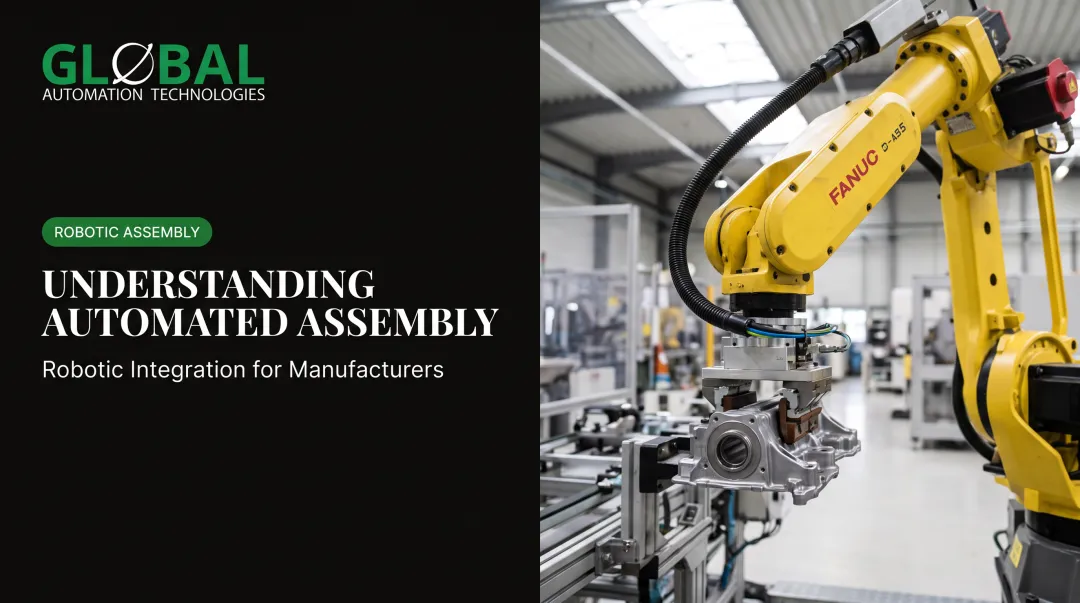
Ask "what is pneumatic in robotics?" and the answer, most of the time, is the gripper. Pneumatic cylinders and grippers are the most common form of end-of-arm tooling (EOAT) on robotic arms, handling the gripping, clamping, and part transfer that a robot's arm alone can't do.
Pneumatics pairs well with robotics for a few clear reasons:
- Fast cycle times: air-driven grippers open and close in a fraction of a second.
- Lightweight tooling: less mass at the end of the arm means less wear on the robot's wrist and faster acceleration.
- Repeatable motion: ideal for high-volume, repetitive tasks like machine tending and material handling.
Modern pneumatic valve terminals now come with fieldbus and IoT connectivity built in, letting a robot controller or PLC talk directly to individual valves. That means a robotic cell can synchronize gripper timing with motion path, machine interlocks, and quality checks, all from one data stream instead of a tangle of individually wired solenoids.
That connectivity layer is where GLOBAL Automation Technologies comes in. As a 17-plus-year, Level 5 FANUC Authorized System Integrator with a proven global base of robotic deployments, GLOBAL designs and builds complete robotic cells. Those cells include pneumatic EOAT and grippers for machine tending, material handling, and assembly on FANUC platforms built for high-precision manufacturing.
GLOBAL adds a practical layer most integrators don't offer. Its automation solutions and engineering services design and commission the robotic-pneumatic cell, while its technical staffing places controls engineers, robot programmers, and technicians on-site to run and maintain it long after startup. For a manufacturer, that means the same organization that engineered the gripper logic can also supply the technician who troubleshoots it six months into production.
Frequently Asked Questions
What is pneumatic automation?
Pneumatic automation is the use of compressed air to power and control mechanical motion in automated equipment, such as cylinders, actuators, and grippers. Shops use it when they need fast, repeatable motion without the cost or complexity of a full electric axis.
How is pneumatics used in robotics?
Pneumatic cylinders and grippers are commonly used as end-of-arm tooling on robotic arms. They provide fast, lightweight gripping and part handling for tasks like machine tending and assembly.
What is the difference between pneumatic and automatic?
Pneumatic refers to the power source, compressed air. Automatic refers to the control method, a system operating without manual input. A pneumatic system can be manual, semi-automatic, or fully automatic.
What is the difference between pneumatic and hydraulic systems?
Pneumatic systems use compressed air; hydraulic systems use incompressible fluid, usually oil. Pneumatic systems favor speed, simplicity, and low cost, while hydraulic systems favor much higher force output.
What are the main components of a pneumatic system?
The core building blocks are the air compressor, FRL air preparation unit, control valves, actuators, and sensors. Together they generate, condition, route, and convert compressed air into motion.
Is pneumatic automation still relevant alongside modern electric and robotic systems?
Yes. Pneumatics remains widely used alongside robotics and electric automation for cost-effective, high-speed, safe motion control, especially in end-of-arm tooling on robotic cells.