
Introduction
Designing a control system means defining clear objectives, modeling how the system actually behaves, and selecting the right control strategy and hardware. Then you validate everything before it runs your production line. Skip any of those steps, and you're gambling with uptime.
This guide is for manufacturing engineers, controls engineers, and plant managers who design or upgrade automated production and robotic systems. In those environments, reliability, safety, and precision aren't optional extras.
Too many teams reduce control system design to "picking a PID controller." In reality, it's a series of interconnected engineering decisions, each one affecting the next. Below, we walk through the basic steps, the factors that shape them, and the mistakes that derail projects.
Key Takeaways
- Design follows seven steps: define objectives, model, select strategy, choose hardware, simulate, implement/tune, and monitor
- Skipping requirements or simulation drives rework, delayed startups, and unplanned downtime
- System dynamics, environment, and safety requirements shape every hardware and strategy choice
- AI-assisted simulation and predictive maintenance are compressing design and commissioning timelines
What Is Control System Design and Why It Matters
Control system design is the process of specifying the architecture, algorithms, sensors, and actuators needed to make a dynamic system behave predictably, even when inputs and disturbances change. Done well, it keeps the system stable across operating conditions while holding down:
- Error from setpoint
- Overshoot
- Response delay
This differs from general product or mechanical design in one key way. Control design governs input-to-output behavior, not structural integrity or appearance. A robot arm can be mechanically flawless and still perform poorly if the underlying control logic is wrong.
Why it matters in manufacturing: Downtime keeps getting costlier. Siemens reported that unproductive hours for automotive manufacturers cost $2.3 million each in 2024, a 113% jump from 2019. That rise far outpaced general U.S. price inflation over the same period.
Not every dollar of that loss traces to control design. Still, poor tuning, weak feedback, or a controller that cannot reject real-world disturbances show up the same way:
- Deviations from setpoint
- Scrap and rework
- Stopped lines
Those failure modes are why the design steps that follow matter as much as the mechanical hardware around them.

The Basic Steps in Designing a Control System
Control system design isn't a single linear pass. It's an iterative cycle from requirements definition through deployment and ongoing refinement, with several steps overlapping in practice.
Simulation, for example, often runs in parallel with hardware selection rather than after it. Most projects still follow this sequence:
Step 1: Define Control Objectives and System Requirements
Before any technical design begins, establish measurable performance targets:
- Accuracy and tolerance — how tight does the output need to be?
- Response time — how fast must the system react to a change?
- Throughput — what production rate must the system sustain?
- Constraints — safety, regulatory, and environmental limits
Process engineers and controls engineers need to align on production goals here, not after the hardware is ordered. ISA maintains an entire standard, ISA-5.06.01, dedicated to functional requirements documentation for control software, which reflects how much design trouble stems from vague or missing specs.
Step 2: Model the System or Process Dynamics
Next, build a mathematical or simulated model of the plant, machine, or robot cell to predict how it responds to inputs and disturbances. This step determines whether you're dealing with a linear or nonlinear system, which directly shapes controller selection later.
Don't shortcut this step. NIST researchers warn that neglecting nonlinearities in a control system model can cause unsatisfactory performance or outright instability.
Dead zones, communication delays, and rate constraints all behave differently than a clean linear model predicts. Test whether your assumptions hold across the entire operating range, not just at the nominal point.
Step 3: Select the Control Strategy and Controller Type
With a model in hand, choose among control strategies based on system complexity and required precision:
- PID control — simple, reliable, ideal for single-loop regulation
- PLC-based logic — sequential control for discrete manufacturing operations
- Model predictive control (MPC) — multivariable, constraint-aware control for interacting, delayed processes
The trade-off is consistent across all three: ease of tuning versus performance in demanding applications. PID remains the default for good reason, but MPC earns its complexity when a process has multiple interacting variables and hard operational constraints.
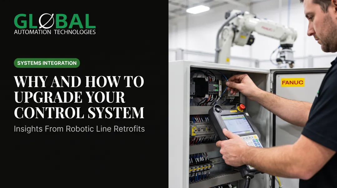
At GLOBAL, controls engineers build on top of FANUC's native controller platforms, layering in PLC integration for material handling and conveyor coordination, and closed-loop feedback for dispensing applications where flow rate, gun parameters, and robot speed all need to move together.

Step 4: Choose Sensors, Actuators, and Hardware Architecture
Hardware selection has to match both the process and the environment. A sensor rated for a clean assembly line won't survive a welding cell or paint booth.
Consider:
- Accuracy and speed — sensor must keep pace with cycle time
- Durability — hardware must survive heat, vibration, and contamination
- Environmental rating — match hazardous-location class and enclosure type
- Architecture fit — PLC, robot controller, or industrial PC matched to conditions
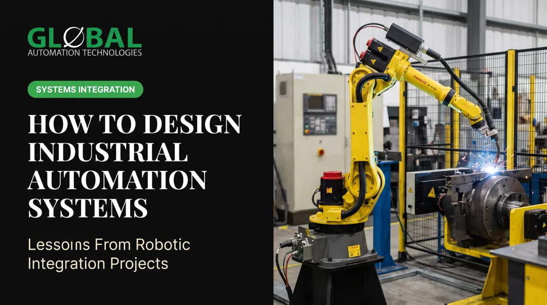
Paint booths, for instance, demand intrinsically safe designs because of flammable solvents and atomized coatings in the air. Welding cells need ruggedized, shielded hardware to handle spatter, heat, and electromagnetic interference.
GLOBAL's paint robot integrations use FANUC platforms built for these hazardous spray environments, with hollow-wrist cable routing to protect wiring from overspray and chemical exposure.
Step 5: Simulate and Validate the Design Before Deployment
Before committing to a physical build, simulate the controller's performance against your original requirements. This is where costly on-site surprises get caught early, while they're still cheap to fix.
GLOBAL, which holds Level 5 status in FANUC’s Authorized System Integrator program, uses AI-assisted simulation to model, test, and optimize robot programming and control logic before a single line of code runs on the plant floor. This approach has compressed what used to take weeks of programming into days, translating into faster startups and fewer surprises during commissioning across welding, painting, dispensing, and material handling projects.
Step 6: Implement, Program, and Tune the Controller
Now install the system, program its logic, and tune parameters against real-world response. First-pass tuning almost never hits final performance targets on the first try, and that's normal, not a red flag.
Expect iteration:
- Install and power up the control hardware
- Load and run initial control logic
- Compare actual response against target performance
- Adjust tuning parameters
- Retest and repeat until targets are met
Step 7: Commission, Monitor, and Continuously Optimize
Final commissioning includes acceptance testing against your original requirements. But the work doesn't stop once the line is running.
Ongoing monitoring for drift, wear, or shifting production conditions is what keeps a well-designed system performing well long-term. GLOBAL's AI-driven predictive maintenance health assessments continuously flag equipment issues before they escalate into unplanned downtime, protecting both production schedules and maintenance budgets.
Key Factors That Influence Control System Design
Several recurring factors shape every design decision above:
- System dynamics and inputs — linear vs. nonlinear behavior, and how disturbances add complexity to the required controller
- Operating conditions — temperature, vibration, and hazards (paint booths, welding cells) that drive sensor, actuator, and enclosure choices
- Equipment and integration dependencies — compatibility with existing PLCs, SCADA systems, or robot controllers already on the plant floor
- Scale, throughput, and cycle time — high-volume automotive or Tier 1 supplier lines demand faster response and tighter tolerances than low-volume operations
- Safety and regulatory constraints — functional safety standards and robotics safety requirements that drive redundancy, guarding, and fail-safe design choices
Safety and regulatory constraints belong in the architecture phase, not at the end. ISO 10218-1 and ISO 10218-2 (updated in 2025) govern industrial robot safety and robot cell integration; IEC 62061 and ISO 13849 cover broader machinery safety-related control systems. Build guarding, redundancy, and E-stop design around them from the first pass.

Common Mistakes to Avoid When Designing a Control System
Most control system failures trace back to one of these three shortcuts:
- Skipping upfront requirement definition. Jumping straight to controller selection without documented, measurable specs almost guarantees a mismatch between what the controller does and what production needs.
- Treating simulation as optional. A Control Engineering survey of over 1,800 system integrators found that as much as 80% of automation project problems stem from inadequate client-integrator communication. Specs and expectations never validated in simulation show up later as costly on-site reprogramming and delayed startups.
- Assuming "set and forget" after commissioning. Control systems drift. Sensors wear. Production conditions change. Without ongoing monitoring, small deviations turn into unplanned downtime before anyone notices.
Conclusion
Designing a control system is a structured, iterative sequence—not a single technical decision. Work through it in order:
- Define objectives and model the system
- Select the control strategy and hardware
- Simulate, implement, and tune
- Monitor performance after deployment
Skip modeling, simulation, or post-deployment monitoring, and you build in risk that usually surfaces at the worst time.
An integrator that combines simulation expertise, robotics hardware knowledge, and engineering talent under one roof removes the handoff gaps that create that risk. GLOBAL Automation Technologies manages the full lifecycle in-house—from process study and offline simulation through controls engineering, commissioning, and long-term support—so design decisions stay consistent from concept to the plant floor.
Frequently Asked Questions
What are the 4 components of a control system?
A typical feedback loop consists of a reference/setpoint, a controller, an actuator or final control element, and a sensor providing feedback. The controller compares feedback against the setpoint and adjusts the actuator to close the gap.
What are the steps in designing a good control system?
Define requirements, model the system, select a control strategy, choose hardware, simulate, implement and tune, then monitor. Each step feeds into the next, and several overlap in real projects.
What's the difference between open-loop and closed-loop control systems?
Open-loop control acts without feedback—the output stays fixed until someone changes it. Closed-loop control continuously adjusts output from measured results and corrects for disturbances automatically.
How long does it typically take to design and commission an industrial control system?
Simple cell upgrades may take weeks; full production-line systems often run several months from design through commissioning. Simulation-driven design shortens that timeline by catching issues before physical build.
What is a PID controller and why is it so widely used?
A PID controller adjusts output using proportional, integral, and derivative error terms. It is the most common industrial controller because it is simple to implement and reliable on everything from temperature loops to motion axes.
How is a control system tested before it goes into full production?
Testing usually moves through simulation, staged hardware checks, and formal acceptance testing against the original performance requirements. Each stage catches problems earlier—before full-scale rollout.