
Introduction
Programming complexity remains the primary barrier to robotic welding automation. Robots are more reliable and affordable than a decade ago, but programming still demands both welding process knowledge and robotics expertise. Most plants do not have that combined skill set on staff.
Research from the American Welding Society notes that complexity in programming, calibration, and setup has long meant specialized skills and extended commissioning times. FANUC case studies make the same point: successful arc welding automation needs integrated welding and robotics expertise that most production teams lack.
This guide covers:
- Core programming methods used on the plant floor
- Technical concepts every engineer should master
- Best practices and common mistakes to avoid
- Practical ways to build programming capability in-house
Key Takeaways
- Match the method to the job: teach pendant, offline, or hand-guided, by volume and skill level
- Calibrate Tool Center Point (TCP) and coordinate systems first to avoid costly positioning errors
- Check fixtures, fit-up, and hardware before editing code—many "programming" faults start there
- Validate with AI-assisted simulation to cut programming time from weeks to days
- Plan months of dual training in welding process knowledge and robotics to build internal expertise
Understanding Robotic Welding Programming Methods
Manufacturers have three primary approaches to programming welding robots: teach pendant programming, offline programming, and hand-guided/collaborative programming. Each method uses a different interface to create the robot's motion path and weld parameters, but all three drive the same robotic system.

Teach Pendant Programming
Teach pendant programming uses the robot's handheld controller to manually jog the torch into position and record points along the weld path. FANUC's tablet teach pendant teaches points on a timeline, builds simple logic, and shows motion paths at the robot. With welding software integrated, you can also adjust voltage, wire feed speed, and travel speed from the same controller.
Best for:
- Production environments where you're teaching points at the installed cell
- On-the-fly adjustments during commissioning or changeovers
- Shops without CAD models or detailed part geometry
- Teams with direct access to the robot during setup
Offline Programming (OLP)
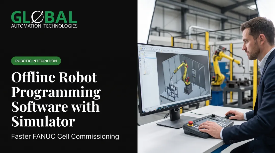
Offline programming creates robot programs in simulation software away from the production floor. FANUC's WeldPRO builds arc-welding workcells from imported tooling and workpiece CAD. It defines paths, torch angles, and parameters, then visualizes reach, access, and sequencing before you transfer the program to production. ABB's ArcWelding PowerPac generates weld positions plus approach and departure points directly from CAD geometry.
Best for:
- CAD-defined parts where geometry is already digitized
- High-volume operations where robot downtime is expensive
- Complex parts requiring extensive reach and access validation
- Multi-robot or coordinated welding cells with intricate sequencing
That downtime and complexity pressure is why GLOBAL pairs AI-assisted simulation with offline programming. Engineers model, test, and optimize paths before deployment, cutting programming time from weeks to days and reducing surprises at commissioning.

Hand-Guided/Collaborative Programming
Hand-guided welding lets operators physically move the torch and wire into the joint position and use simplified hand-guidance controls to create the program. FANUC explicitly positions this method for high-mix, low-volume shops and small-batch parts where welders should not need conventional pendant-jogging proficiency.
Best for:
- Small collaborative robots in lower-volume production
- Shops with skilled welders but limited robotics programming experience
- High-mix environments with frequent part changeovers
- Operations prioritizing ease of teaching over cycle-time optimization
Important limitation: Hand guidance simplifies the teaching interface but does not eliminate the need for welding process knowledge. You still must understand heat input, torch angles, joint preparation, and weld sequencing to program effectively.
Essential Programming Concepts Every Engineer Should Master
Tool Center Point (TCP)
The Tool Center Point (also called the User Tool Frame) is the precise location of the torch tip relative to the robot's wrist. FANUC defines it as the point the tool rotates about as all six axes move. Incorrect TCP calibration causes positioning errors that compound across the entire weld path, so bead placement drifts even when the program itself is correct.
When to recalibrate TCP:
- After any torch or gun-neck change
- Following a collision or crash
- When you see unexplained location errors
- Before starting a new production program
Bernard/Tregaskiss troubleshooting guidance confirms that a bent robotic MIG-gun neck can cause TCP error. The recommended response is to use a neck-checking and alignment tool, verify neck and consumable installation, then recalibrate TCP before editing program points.
Motion Types
Robots use different motion commands depending on whether they're welding or moving between joints:
- Linear moves (
MoveL): Hold a precise straight-line path between points; use these during welding to keep the torch on the joint - Joint moves (
MoveJ): Move each axis independently along the fastest path; use these for air moves between welds when torch path does not matter - Circular moves (
MoveC): Follow a defined arc or radius for curved weld paths and corner transitions
Wrong motion choice shows up fast: joint moves through a weld seam create path error, while linear moves for every air travel inflate cycle time.
Coordinate Systems
Every robot program references at least three coordinate systems:
- Base coordinates: Relative to the robot's mounting point. This frame is the foundation for every other coordinate system.
- User/workobject coordinates: Relative to the fixture or part. ABB's coordinate system documentation explains that robot targets are related to a workobject's object frame. If the real fixture differs from the offline station, adjusting the workobject can recalibrate the entire offline program without editing every individual target.
- Tool coordinates: Relative to the torch tip (the TCP). This frame moves with the torch as the robot articulates, so you can program weld paths from the torch's point of view.

Work Envelope and Reach Limitations
The work envelope defines the robot's physical reach. Positions outside that envelope cause faults. Singularities are just as problematic: robot axes align in ways that make smooth motion impossible and produce jerky paths.
FANUC WeldPRO and Yaskawa's MotoSim both support reach studies and cell-layout validation before deployment, so you can catch these issues in simulation rather than on the production floor.
Weld Parameter Control
FANUC's ArcTool couples path motion with arc start/stop, wire feed speed, voltage, and current. Fronius/Yaskawa integration records current, voltage, and wire speed by seam, provides process libraries and editable jobs, and exposes live parameters at the robot pendant.
Control is split across two systems:
- Robot controller: Travel speed and torch path
- Power source: Voltage, current, and wire feed
Effective programming coordinates both: motion parameters in the robot controller and weld schedules in the arc-file library.
Best Practices for Efficient Weld Programming
Efficient weld programs share a few habits: modular structure, fast air moves, positions taught for real fixtures, and shared parameter libraries. Build those in early and cycle time, uptime, and handoffs all improve.
Keep Programs Simple and Modular
Break complex welding sequences into logical subroutines with clear, descriptive names. Tools such as ABB's Production Manager support setup and service routines, work areas, and PLC- or operator-initiated jobs so programs stay organized and maintainable.
Key practices:
- Use consistent naming conventions across all programs
- Add comments explaining non-obvious logic or special conditions
- Create reusable subroutines for common weld sequences
- Document any deviations from standard procedures
Optimize Motion for Cycle Time
Use joint moves for all non-welding air movements. They're faster because each axis takes the shortest path instead of holding a straight-line path. Minimize unnecessary torch reorientation between welds, and plan paths that cut total travel distance.
Yaskawa's offline tools support cycle-time estimation during programming so you can compare sequencing options before you lock a final program.
Program for Real Production Conditions
Account for fixture interference, clamp locations, part variation, and operator access when teaching positions. Lincoln Electric's research warns that weak tooling and part prep can pull joints off the programmed path.
Touch sensing can cover expected variation, but it typically adds 3–5 seconds per joint. Use it only where that variation is worth the cycle-time cost.
Establish and Maintain Arc File Libraries
Create reusable weld parameter sets by joint type, material, and thickness, with clear naming conventions. Fronius/Yaskawa systems and similar platforms keep those jobs in process libraries you can edit, compare, and restore.
Store controlled, documented weld schedules instead of burying raw parameter values in motion code. Troubleshooting gets faster, and multiple programmers stay consistent on the same cell.
Common Programming Mistakes to Avoid
Most weld quality and uptime problems blamed on “bad code” come from process, hardware, or cell setup. Catch these four mistakes early and you spend less time rewriting paths that were never the root cause.
Assuming the Program Is the Problem
Most weld defects trace back to part fit-up, fixture positioning, consumable wear, or grounding problems—not the robot program. Bernard/Tregaskiss troubleshooting guidance recommends starting with the most recent process, equipment, or program change, then checking consumables before editing the path.
Systematic troubleshooting order:
- Verify TCP calibration hasn't changed
- Check consumable condition and installation
- Inspect cables for damage, kinking, or routing issues
- Verify fixture and part positioning
- Review grounding and electrical connections
- Only then consider program changes

Creating Singularities
FANUC defines singularities as points where multiple kinematic solutions exist for one endpoint. The robot can fault if it cannot select a solution. Singularities most commonly occur when J5 (the wrist pitch axis) approaches zero degrees, aligning multiple axes.
How to avoid:
- Review robot posture during path planning
- Redesign the path to avoid problematic positions
- Adjust tooling or cell geometry to change approach angles
- Use manufacturer singularity-avoidance options where available
Ignoring Cable Management and Collision Paths
Programs that work in ideal conditions can still damage equipment when cables snag on fixtures or the torch hits clamps. Walk the full motion sequence and confirm:
- Cable path and length stay clear through every move
- No bunching, kinking, or rubbing on tooling
- Torch and dress pack cannot catch on clamps or components
Reprogramming Around Damaged Hardware
After a collision, inspect the gun neck and consumable installation before retouching program points. A bent neck changes the TCP, so recalibrating around the damage just embeds the error in your program. Fix the hardware, recalibrate the TCP, then validate the original program.
Reducing Programming Time Through Technology
AI-assisted simulation and offline programming let engineers model, test, and optimize robot paths before a program ever runs on a live cell. GLOBAL, which holds Level 5 status in FANUC’s Authorized System Integrator program, uses these tools to catch reach problems, collisions, and weak motion strategies early—cutting programming time from weeks to days.
Key advantages:
- Virtual validation: Test programs without tying up production equipment
- Reach and access analysis: Identify unreachable positions or interference before building fixtures
- Cycle-time optimization: Compare sequencing options and motion strategies in simulation
- Error detection: Catch singularities, collisions, and logic errors before commissioning
Simulation removes most trial-and-error from the factory floor and cuts scrap during program development. GLOBAL pairs that capability with experienced programming staff through technical staffing, so manufacturers get both the tools and the people who can apply them on the line.
Building Programming Expertise in Your Team
The Dual-Skill Requirement
Effective welding robot programmers need both welding process knowledge (heat input, torch angles, joint preparation, travel speed) and robotics programming skills. AWS Certified Robotic Arc Welding (CRAW) certification requires at least six months of manual or semiautomatic arc-welding experience plus an OEM-equivalent robotic programming course. That dual pathway is intentional.
The FANUC production case shows how scarce that blend is in practice. Welding and robotics each demand their own expertise, and the combined skill set takes months to build—not a one-week course.
Practical Training Approaches
Start with OEM fundamentals. Lincoln Electric's automation training includes FANUC basic, intermediate, and advanced courses (5 days each), and ABB basic and advanced courses (4 days each). OLP training requires basic robot training, GMAW experience, and PC literacy as prerequisites.
Build skills in stages:
- Welding-process foundation (6+ months manual welding experience)
- OEM basic programming course (4-5 days)
- Supervised hands-on cell exercises
- Advanced or offline programming training
- AWS CRAW-aligned validation

Pair new programmers with experienced mentors. Mentorship speeds learning and prevents costly mistakes during the months-long jump from trained to proficient.
Addressing the Skills Shortage
Qualified robot programmers remain scarce across manufacturing. GLOBAL addresses that gap by delivering both the robotic system and experienced programming staff through technical staffing. Options include contract, contract-to-hire, or permanent placement of robot programmers, controls engineers, and commissioning specialists.
Manufacturers get the system and the people to program and maintain it in one engagement—without waiting months to train internal staff or competing for scarce talent in a tight labor market.
Frequently Asked Questions
How long does it take to program a robotic welder?
Programming time depends on part complexity, weld count, fixture design, and programmer experience. Simple linear welds may take 30 minutes to a few hours; complex multi-position programs with sensing can take several days. Offline programming and simulation tools shorten that timeline.
What programming language do welding robots use?
Each brand uses a proprietary language: ABB uses RAPID, KUKA uses KRL, Yaskawa uses INFORM, and FANUC uses TP. Programs do not transfer between brands without a full rewrite.
Can you program a welding robot without coding experience?
Modern teach pendants and hand-guided programming use graphical interfaces, so you don't need traditional text coding. You still need motion logic, sequencing, coordinate systems, and weld-process fundamentals to build effective programs.
What is TCP in robotic welding programming?
Tool Center Point (TCP) is the precise location of the torch tip relative to the robot's wrist. The robot uses this reference to calculate all motion paths. Recalibrate TCP after torch changes, collisions, or unexplained positioning errors—bad TCP compounds error across the full weld path.
How do you optimize welding robot cycle time?
Use joint moves for air travel, cut unnecessary torch reorientation, sequence welds to shorten travel, and raise air-move speeds in safe zones. Offline simulation lets you compare sequences and validate cycle-time gains before production.
Do I need offline programming software for robotic welding?
Offline programming pays off for high-volume cells, complex reach validation, or CAD-defined geometry where robot downtime is costly. Teach pendant programming is often enough for job shops, lower-volume work, and simpler parts.