
Automation equipment design isn't a single discipline. It's mechanical engineering, electrical engineering, controls architecture, and software development happening at once — not a sequence of handoffs. Get the coordination wrong, and even a mechanically sound cell can stall out during commissioning because the controls logic wasn't planned in parallel.
This guide breaks down the engineering, planning, and partnership decisions manufacturers need to nail down before committing capital to a custom automation cell.
Key Takeaways
- Requirements, KPIs, and application fit must be locked in before any component gets ordered.
- Mechanical, electrical, and controls engineering must work as one integrated design effort, not siloed departments.
- Simulation and digital twins catch expensive design flaws before physical fabrication starts.
- Flexibility, safety, and maintainability choices at the design stage decide how long a system stays useful.
- The best design partners deliver the system and the staff to run it afterward.
Start With Requirements, Not Robots
Skipping a rigorous requirements phase is one of the most common ways automation projects go sideways. Automation World has flagged the "ready-fire-aim" approach (jumping to equipment selection before defining the problem) as a direct driver of cost overruns and schedule delays. ASSEMBLY's project management guidance is blunt about it too: change orders that stem from undefined requirements cost real time and real money.
Across manufacturing engineering literature, the pattern holds: projects that skip requirements definition pay for it later, usually during commissioning, when fixes cost the most.
Aligning Automation with Business Goals, Not Just Engineering Feasibility
Technical feasibility alone is not enough. The decision needs to weigh:
- Production volume — is there enough throughput to justify the capital?
- Product lifecycle maturity — is the design still changing?
- Changeover frequency — how often does the process need to flex?
A low-volume product still going through rapid design iteration is a classic case where full automation is premature. Locking tooling and programming around a part geometry that changes every few weeks usually means re-engineering the cell before it has paid for itself.
In those cases, a cobot tending setup often beats a fully automated cell. It keeps flexibility for high-mix, lower-volume work where adaptability matters more than raw throughput.
Establishing KPIs and Operational Benchmarks Before Design Begins
Before design work starts, manufacturers should define the operational metrics that will later serve as acceptance criteria:
- Overall equipment effectiveness (OEE) targets for the new cell
- Cycle time and throughput velocity expectations
- Accuracy and repeatability requirements
- Break-fix frequency tolerances
These numbers become the yardstick the finished system is measured against at sign-off.
NIST research on manufacturing automation found that smaller manufacturers typically look for a 1-2 year payback window on robotic equipment. Well-designed machine tending cells often land inside that range in 12 to 18 months through higher spindle utilization, fewer manual load cycles, and labor moved to higher-value inspection and programming. Clear KPIs upfront make that payback measurable instead of aspirational.
Clarifying Application and Environment Requirements
Every application has constraints that shape the mechanical and safety design of the cell, and they need to be documented, not assumed:
- Payload and reach — part and tooling combined, not the part alone
- Cycle time — targets under realistic production conditions
- Hazardous environment factors — paint booths, welding fume zones, dispensing operations
Skip this step and you risk sizing a robot for the part alone, forgetting that the end-of-arm tooling, hoses, or process equipment add weight and reach demands that change the platform selection entirely.

Engineering the System: Mechanical, Electrical & Controls Integration
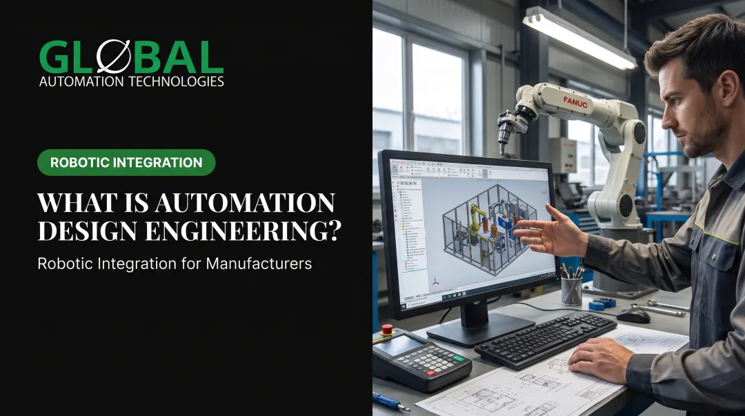
A mechanically flawless design can still fail if controls logic and wiring weren't planned in parallel. Automation equipment design works best when mechanical, electrical, and controls engineers are building from the same specification simultaneously — not passing a finished mechanical design over the fence for controls to figure out afterward.
The mechanical choices below drive electrical layout, I/O mapping, and controls logic, so they have to be locked with those teams—not handed off after the fact.
End-Effector and Gripper Design
Gripper and end-of-arm tooling selection depends on part geometry, fragility, and required speed. There's no universal gripper. A custom tool built around a specific part's weight distribution and structural weak points will always outperform an off-the-shelf option pulled from a catalog.
Vision-guided and sensor-equipped grippers have closed a lot of the gap with human dexterity for delicate parts. Systems that combine 3D area sensing with custom EOAT let a robot locate and orient a part before contact, whether it sits in a bin, on a rack, or moves down a conveyor. That pre-contact sensing cuts misalignment and impact damage risk.
Part Presentation, Nesting, and Tolerance Control
"Nesting" refers to how parts are held and positioned for consistent automated handling. "Crowding" describes what happens when parts are packed too tightly for a robot to pick reliably. Both need to be solved at the design stage, not patched on the floor later.
Tightening tolerances during design, rather than discovering the issue during commissioning, reduces:
- Scrap from misfeeds or misgrips
- Troubleshooting time during startup
- Downstream rework caused by inconsistent part orientation
Material Flow, Staging, and Supply Readiness
Material staging and part-feed systems get underestimated more often than any other piece of an automation cell. A perfectly engineered robot can still sit idle if the parts aren't staged in a way that matches its cycle time.
This isn't a bolt-on afterthought. Design it in lockstep with the robot cell itself: part presentation, sequencing logic, and buffer capacity for multi-machine tending setups.
Selecting the Right Robotic Platform for the Application
Platform choice has to match the application's actual demands, not just its category. FANUC's platform lineup illustrates this well:
| Application | Platform Considerations |
|---|---|
| Painting/coating | Hazardous spray environments; intrinsically safe design; hollow-wrist cable routing |
| Dispensing/sealing | Payload and reach scaled to process gear; servo dispensing via the robot controller |
| Machine tending | Light parts handling through heavy CNC loading, by part weight and machine envelope |
Matching payload, reach, wrist access, and controller compatibility to the actual process (including tooling and hose weight) is what separates a cell that runs reliably from one that's constantly fighting its own hardware limits.

Validate Before You Build: Simulation, Testing & Digital Twins
CAD/CAE simulation tools let engineers predict how equipment will behave before a single part is fabricated. Design flaws get caught cheaply on a screen instead of expensively on the shop floor during commissioning.
A digital twin takes this further: the entire assembly or process sequence gets simulated virtually, verified in real time, and refined before it ever touches the physical floor. Rockwell Automation's Emulate3D deployment with ECM Technologies is a solid real-world example. The team simulated and tuned PLC code before delivery, and Rockwell reports up to five months removed from project lead time with 50% shorter commissioning as a result.
AI-Assisted Simulation Is Changing Startup Timelines
AI-assisted simulation is compressing what used to be weeks of robot programming into days. Rather than writing and testing code live on the production floor, engineers now model, test, and optimize robot programs entirely in a virtual environment before deployment. That catches path conflicts, cycle time issues, and logic errors before they cost real downtime.
ABB's own data shows how large this shift is. The company's RobotStudio HyperReality platform claims commissioning time reductions of up to 80% through physics-accurate virtual line design.
GLOBAL Automation Technologies, which holds Level 5 status in FANUC’s Authorized System Integrator program, applies the same simulation-first approach across its engineering practice. Robot paths and logic are modeled, tested, and optimized virtually before anything runs on physical equipment, which cuts startup surprises and keeps commissioning on schedule.
Building in Testing and Acceptance Milestones
Formal acceptance testing criteria need to trace directly back to the KPIs set during the requirements phase. Without that link, sign-off becomes subjective. With it, the system is validated against real business objectives, not just whether it runs.
Typical acceptance milestones include:
- Throughput targets tied to production volume goals
- Accuracy and repeatability thresholds for critical operations
- Uptime and reliability requirements for sustained operation
Design for the Long Run: Flexibility, Safety & Maintainability
Not every station needs full automation. Blending manual and automated steps can reduce technical risk and cost while preserving flexibility for part variation or future product changes, particularly for steps where the process itself is still being proven out.
Safety-by-design means building in guarding, e-stops, and planned responses to abnormal conditions from day one, not retrofitting them after an incident. This matters most in hazardous processes:
- Painting and coating operations expose workers to isocyanates and VOCs, both linked to respiratory and skin health risks by OSHA and NIOSH
- Welding generates fumes and spatter requiring source-capture ventilation positioned close to the arc
Equipment design that removes operators from the booth or the weld zone entirely, rather than relying on PPE alone, is the more durable solution.
Maintainability deserves the same upfront attention. AI-driven predictive maintenance and equipment health assessments, designed into the system from the start, flag developing issues before they cause downtime. Documented results include:
- BlueScope avoided roughly 2,000 hours of unplanned downtime over three years using predictive analytics (Siemens)
- A cement facility cut unplanned downtime by 56% with intelligent equipment monitoring (World Economic Forum)
Finally, build in contingency: extra station space, manual fallback points, and buffer capacity for unproven process steps. High-risk operations identified during design deserve a plan B built into the layout, not bolted on after a failure.

Choosing the Right Automation Design Partner
Few manufacturers have deep in-house bench strength across mechanical, electrical, controls, and robotics engineering all at once. That makes the choice of design and integration partner one of the highest-leverage decisions in the entire project.
Prioritize full-stack engineering depth, validation before install, and a plan for who runs the cell after handoff. A finished cell with no one trained to support it is a common and costly failure mode.
Most automation firms do either systems integration or staffing, but not both. GLOBAL Automation Technologies was built around that gap, combining automation solutions, services and technical staffing, so manufacturers get the engineered system and the engineers qualified to run, program, and maintain it.
GLOBAL's turnkey capability spans:
- Layout and conceptual design
- Mechanical, controls, and robot programming
- Simulation and validation
- Installation and commissioning
- Operator and maintenance training
- Ongoing technical support
With 17+ years in operation and a proven global base of robotic deployments across automotive, Tier 1 supplier, and heavy industry applications, GLOBAL's principle is simple: validate the design before it hits the floor, then keep someone qualified there to run it.
Frequently Asked Questions
What is automation equipment?
Automation equipment covers the hardware and software that make up a manufacturing cell — robotic arms, conveyors, sensors, PLCs and controllers, end-effectors or grippers, and vision systems. These components work together to handle, move, inspect, or process parts without manual intervention.
What are the four types of automation?
Three classic types plus one systems-level category:
- Fixed (hard): Fixed sequence, high investment, high output
- Programmable: Reprogrammed between batch runs of different products
- Flexible: Rapid, automatic changeover without batching
- Integrated: Ties cells into broader enterprise data systems (MES/ERP), not a separate hardware class
What are the 5 layers of automation?
The automation pyramid is usually described in five layers: field/device (sensors and actuators), control (PLCs), supervisory (SCADA), MES, and ERP. Design choices at the field and control layers determine how cleanly data moves up the stack.
What is the most important factor to consider when designing automation equipment?
Clearly defined requirements and KPIs before design begins have more impact on project success than any single mechanical or software choice. Without them, even well-engineered systems get judged against a moving target.
How long does it typically take to design and deploy custom automation equipment?
Most custom cells take several months from concept through commissioning, depending on scope and integration complexity. Simulation-driven design often cuts on-floor programming from weeks to days by validating the process virtually first.
What is Design for Automated Assembly (DFAA)?
DFAA means designing parts so automated systems can feed, orient, and assemble them easily — consistent assembly direction, feed-friendly geometry, and tolerances that avoid unnecessary precision. Getting this right in product design prevents costly rework before the cell is built.