
Introduction to Machine Vision and Control Systems in Automation
Manufacturing quality inspection used to mean pulling parts off the line, checking them manually, and hoping the sample represented the entire batch. Today, machine vision systems inspect every part at production speed: they catch defects, verify dimensions, and guide robots without slowing the line.
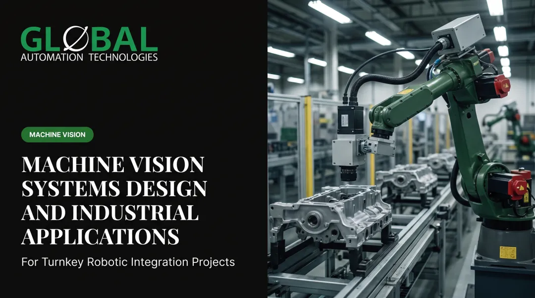
Modern systems pair cameras and lighting with image processing software to handle work that once needed human eyes. They spot surface defects manual inspection misses, measure features to micrometer precision, and guide robots picking randomly oriented parts from bins.
The stack has moved past standalone smart cameras talking to separate controllers. Fully integrated vision-control platforms now run image processing, motion control, and process logic together in real time. That cuts communication delay and delivers the microsecond synchronization high-speed automotive assembly and electronics lines demand.
This article breaks down how machine vision and control systems work together, where manufacturers put them to use, and what matters when you specify a solution.
Key Takeaways
- Vision systems combine cameras, lighting, and image processing to inspect quality and guide robots at production speed
- Integrated vision-control platforms cut communication delays and enable real-time decisions that raise throughput
- Plants deploy them for quality control, robot guidance, measurement, and track-and-trace in auto, electronics, food, and pharma
- AI vision finds complex defects with little training data; BMW trained models overnight on about 100 images per feature
Core Applications of Machine Vision in Manufacturing
Quality Inspection and Defect Detection
Vision systems perform inline quality control without stopping production. Cameras mounted above conveyors capture images of every part as it passes, while algorithms analyze surface finish, color consistency, and dimensional accuracy in milliseconds.
Inspection runs between process steps (after welding, before coating, or during final assembly), so defective parts are flagged before they reach the next station.
Traditional systems required engineers to program every defect type explicitly. AI-based vision changes that. BMW eliminated false positives from dust and oil by training a neural network on roughly 100 images per condition (good parts, dust, and oil). Training ran overnight, and pseudo-defects stopped triggering rejections.
NIST research confirmed that transfer learning shrinks the image dataset needed for new applications, which makes vision practical for low-volume production and custom parts.
Automotive applications include:
- Paint surface inspection (runs, sags, dirt nibs, craters)
- Body panel gap and flush measurement
- Weld bead verification
- Component presence and orientation checks
Electronics manufacturing uses vision for:
- PCB component placement verification
- Solder joint inspection
- Package seal integrity
- Label and marking validation
Cognex documented 100% line-speed inspection for Knorr, with zero defective items reaching market. A separate pharmaceutical line inspected 72,000 bottles per hour, with full 360-degree imaging available 50 milliseconds after each bottle passed.

Robot Guidance and Positioning
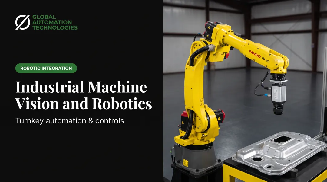
Vision systems tell robots where parts are, how they're oriented, and what type they are. That removes the need for precise feeders and fixtures. Parts can arrive in bins, on racks, or randomly on conveyors, and the robot adapts.
FANUC documented a forging application where two iRVision 3D systems recognize randomly positioned parts and load two ROBODRILL machines. The previous setup used three machines and three operators; the automated cell uses two machines, one robot, two cameras, and one operator.
The vision system finds each forging's location and orientation in the bin, calculates a collision-free pick path, and guides the robot to grasp and transfer the part.
For seam tracking in welding, vision locates the joint in real time and provides adaptive path correction. The robot adjusts its programmed path to match actual part position, compensating for fixture variation and thermal distortion. GLOBAL, a top-tier Level 5 FANUC Authorized System Integrator, integrates seam-tracking vision into robotic welding systems for automotive and heavy equipment, where weld-quality verification can also be added.
Vision-guided applications include:
- Bin picking: Random-orientation retrieval from bulk containers
- Palletizing and depalletizing: Mixed-SKU handling and pattern building
- Assembly guidance: Locating holes, studs, and mating features
- Part transfer: Coordinating pick-and-place between conveyors and machines

Dimensional Measurement and Verification
Vision systems measure part features and compare them to engineering tolerances. A calibrated camera captures the part, edge-detection algorithms identify critical dimensions, and the system records measurements with sub-pixel accuracy.
KEYENCE specifies 0.5–1 µm repeatability and ±10–20 µm accuracy for current 2D/3D measurement systems, with image capture in as little as 0.6 seconds. These systems inspect edges, widths, gaps, positions, and shapes at 100% inline volume: every part, not a sample.
Non-contact measurement avoids the probe wear and setup time of mechanical gauges. Vision can measure features that are inaccessible to contact probes, such as internal diameters, thin-walled sections, and soft materials that deform under pressure. For go/no-go gauging, the system compares measured values to tolerance limits and flags parts outside specification before they reach assembly.
Common applications include:
- Bearing diameter verification
- Gasket profile inspection
- Connector pin spacing
- Label placement validation

Track-and-Trace and Code Reading
Pharmaceutical serialization, automotive traceability, and electronics genealogy all require reading codes on every part. Vision systems use optical character recognition (OCR) and barcode/2D-code reading to capture serial numbers, lot codes, and data-matrix identifiers at production speed.
A Cognex pharmaceutical line reads unoriented bottles through 360 degrees at up to 400 bottles per minute. The DataMan vision system supports up to 90 decodes per second and 1,000 frames per second. One industrial PC manages recipes, security, and audit trails for all smart-camera stations on the line, creating a serialization record for every container.
The FDA Drug Supply Chain Security Act establishes prescription drug product-identifier requirements. Vision systems verify that the required codes are present, readable, and correctly linked to the product. Data flows to MES and ERP systems, building a complete product genealogy from raw material receipt through final shipment.
Vision-Control System Integration Methods
Three common architectures connect machine vision to control systems. Each balances simplicity, scalability, and how tightly vision data couples to PLC logic.
Standalone Smart Cameras
Standalone smart cameras handle simple inspection in one self-contained unit. The camera packs the image sensor, processor, lighting controller, and I/O in a single enclosure. It sends pass/fail results or measurement data to the PLC over Ethernet, serial, or discrete I/O.
They fit fixed tasks such as:
- Barcode reading
- Presence detection
- Simple gauging
They scale poorly when you need multiple views, high resolution, or complex algorithms.
PC-Based Vision Systems
PC-based systems separate the camera from processing. Industrial cameras connect to a vision PC via GigE, USB3, or similar interfaces. Software on the PC runs image processing and reports results to the PLC.
This setup supports:
- Multi-camera inspection
- Advanced algorithms
- Third-party vision libraries
The tradeoff is complexity. Vision and control run on separate platforms and exchange data over a network or fieldbus.
Fully Integrated Vision-Control Platforms
Fully integrated platforms run image processing in the PLC real-time context. Beckhoff's TwinCAT Vision, for example, executes vision algorithms in the same runtime as PLC logic, motion control, robotics, and HMI. Vision data lives in PLC memory, so there are no file transfers and HMI updates are immediate.
Engineers program inspection in IEC 61131-3 languages (Structured Text, Ladder Logic, or Function Block Diagram) instead of proprietary vision tools. That means the same languages already used for motion and process control.
Multi-core industrial PCs often host both control and vision on one platform. Typical Intel Core-i IPCs offer 2 to 8 cores for plant environments, with options for Windows or TwinCAT/BSD, fanless operation, shock and vibration ratings, and extended temperature ranges.
On the plant floor, these architectures only pay off when vision, motion, and controls are engineered together. GLOBAL's AI-assisted simulation tools work with vision systems to cut robot programming from weeks to days. Engineers model, test, and optimize programs before the first cycle runs, pre-validating vision-guided pick paths, tracking sequences, and inspection stations.

GLOBAL integrates FANUC iRVision and 3D area sensors into turnkey cells for automotive, heavy equipment, and industrial manufacturing, coordinating vision with robot motion, conveyor controls, and process PLCs.
Benefits of Integrated Machine Vision Systems
Integrated platforms deliver deterministic reaction times. When vision processing executes in the PLC runtime, the delay between image capture and process action is predictable and measured in microseconds. Beckhoff documents EtherCAT Distributed Clocks synchronizing local clocks to the reference with precision below 100 nanoseconds, enabling coordinated triggering of cameras, motion axes, and I/O.
That synchronization matters in high-speed applications. A bottling line running 400 bottles per minute moves one bottle every 150 milliseconds. If vision-to-PLC communication adds 50 milliseconds of jitter, the system must slow down or risk misalignment. Integrated platforms eliminate the communication step and the associated delay.
Consistency advantages over manual inspection include:
- Extended-shift operation between scheduled maintenance windows, with no shift changes, breaks, or fatigue
- Objective pass/fail criteria applied the same way every cycle
- Complete documentation of every part inspected and every result
- Microsecond decisions that hold at full production rates
Those gains carry onto the plant floor. Safety improves when operators no longer enter hazardous areas for visual checks:
- Robotic painting keeps workers out of spray booths and away from isocyanates, volatile organic compounds, and overspray particulates
- Powder coating cells put robots in high-voltage spray environments instead of people
- Vision-guided material handling automates repetitive lifting and exposure to sharp, hot, or chemically treated parts
GLOBAL's real-time bead quality validation with vision inspection catches material defects before parts move downstream in dispensing applications. The system verifies bead width, placement, and continuity, identifying missed paths, thin beads, and off-spec material during the dispense cycle—not after the part reaches final assembly.
Communication Standards and Camera Connectivity
GigE Vision is the dominant protocol for industrial cameras. It uses standard Gigabit Ethernet hardware—CAT5e or CAT6 cable, standard switches, and RJ45 connectors—and supports uncompressed image transfer over cable lengths up to 100 meters.
Standard GigE implementations provide 1 Gbit/s bandwidth, enough for most single-camera applications. The protocol covers camera discovery, configuration, and image streaming in a vendor-neutral specification maintained by the AIA (Association for Advancing Automation).
For higher data rates, EtherCAT G raises bandwidth to 1 and 10 Gbit/s, supporting multi-camera and 3D vision applications. EtherCAT integration also enables precise trigger timing. The distributed clock synchronizes camera exposure with robot motion, conveyor position, and external lighting within 100 nanoseconds.
Vision-to-PLC communication protocols include:
- EtherCAT: Real-time synchronization and high-speed data exchange
- EtherNet/IP: Common in automotive and general industrial PLCs
- PROFINET: Siemens and European automation platforms
- Modbus TCP: Legacy systems and simple data exchange
- Serial (RS-232C) and USB: Configuration and low-volume data
Smart cameras and vision controllers map to these stacks differently by vendor. Omron FH controllers support EtherCAT, EtherNet/IP, PROFINET, TCP/IP, RS-232C, and USB. Cognex In-Sight systems support EtherNet/IP, PROFINET, SLMP (Mitsubishi), and Modbus TCP.

Selecting Machine Vision Components for Your Application
Resolution follows a simple formula: required pixels = object size / smallest detail to inspect. Calculate horizontal and vertical requirements separately, then select a camera resolution above both.
A 100 mm field of view with a 0.1 mm feature needs at least 1,000 pixels in that dimension. Add margin for edge detection, calibration, and algorithm requirements.
Field of view and working distance drive lens selection. Wide-angle lenses cover large areas but introduce distortion; telephoto lenses work at longer distances but need precise alignment.
Depth of field—the range where the image stays in focus—shrinks as magnification increases. Applications with variable part height may need multiple cameras or telecentric lenses.
Inspection speed sets the frame rate. Basler area-scan cameras range from 10–340 fps depending on interface and sensor size. Higher resolution reduces maximum frame rate, so balance spatial detail against throughput.
Lighting controls usable contrast. Cognex identifies poor lighting as the most common cause of weak machine-vision performance. Lighting geometry increases feature contrast and suppresses glare:
- Backlighting: Silhouettes parts for edge detection and dimensional measurement
- Brightfield (coaxial) lighting: Highlights flat surfaces and inspects reflective materials
- Darkfield (low-angle) lighting: Emphasizes surface texture, scratches, and embossing
- Dome lighting: Eliminates shadows and provides uniform illumination for curved parts
Work with experienced integrators who understand process variability and can specify the right hardware. Camera resolution alone cannot recover a feature that illumination fails to distinguish.

GLOBAL's turnkey integration covers process study, vision-component selection, lighting design, installation, commissioning, and training. Vision systems are validated in the production environment before launch.
Implementation Considerations and Best Practices
Machine learning training duration varies by application complexity and data availability. BMW documented overnight training from approximately 100 images per feature for a crack-versus-dust inspection.
That timeline applied to a specific neural network architecture, dataset, and training environment, not a universal standard. Complex defect libraries, 3D inspection, or multi-model deployments may require weeks or months of data collection, labeling, training, and validation.
Optical setup matters just as much as the model. Calculate resolution from the smallest feature size and field of view, then verify with the algorithm vendor. Sub-pixel edge detection can locate features to fractions of a pixel, but the feature must span multiple pixels for the algorithm to extract it reliably.
Even a well-sized system underperforms if plant conditions work against it. Key environmental factors include:
- Vibration: Mount cameras on isolated structures or use shorter exposure times
- Temperature: Check camera and lighting operating ranges; industrial cameras typically support 0–50°C
- Ambient light: Shield cameras from direct sunlight and overhead fixtures, or use strobed lighting to overpower ambient
- Contamination: Specify IP-rated enclosures for dusty or wet environments; use air purge or wash-down-rated housings where required
Confirm limits on the vendor datasheet rather than assuming generic ranges. SICK Visionary-T specs, for example, list model-level operating and storage temperature limits, enclosure ratings, and performance in speed mode. Match those figures to your production environment before you freeze the design.
Frequently Asked Questions
What is machine vision in automation?
Machine vision uses cameras and image processing algorithms to automate inspection, measurement, and guidance tasks that traditionally required human vision. The system captures images, analyzes them in real time, and triggers process actions such as rejecting defective parts, guiding robot motion, or recording measurement data.
How do vision systems integrate with PLCs and control systems?
Modern vision systems connect to controls over industrial Ethernet and fieldbus networks. Fully integrated platforms run vision algorithms in the PLC real-time environment, cutting separate communication hops and syncing image capture with motion and process logic at microsecond scale.
What are the main benefits of integrated vision systems versus standalone cameras?
Integration eliminates communication latency and enables microsecond synchronization between image capture, motion control, and process actions. Engineers program inspection in familiar PLC languages (Structured Text or Ladder Logic) instead of proprietary tools. Vision data lives in PLC memory for instant HMI display without file transfers.
What industries commonly use machine vision systems?
Automotive, electronics, food and beverage, pharmaceuticals, and logistics are heavy users. Typical jobs include weld and paint inspection, PCB and placement checks, label and fill-level verification, serialization, sortation, and dimensioning.
What communication protocols do vision systems use?
GigE Vision is the dominant camera-to-PC standard, providing 1 Gbit/s over 100-meter cable runs. Vision-to-control communication uses EtherCAT, Ethernet/IP, PROFINET, Modbus TCP, and serial connections depending on the control platform. EtherCAT G raises data rates to 1 and 10 Gbit/s for multi-camera and high-resolution applications.
How much does a machine vision system cost and what is the typical ROI?
Cost hinges on camera count, resolution, lighting, optics, processing platform, integration scope, and validation needs—so quotes for a defined application are the only reliable numbers. ROI usually comes from less scrap, higher throughput, and lower inspection labor, with payback tied to volume and defect cost.