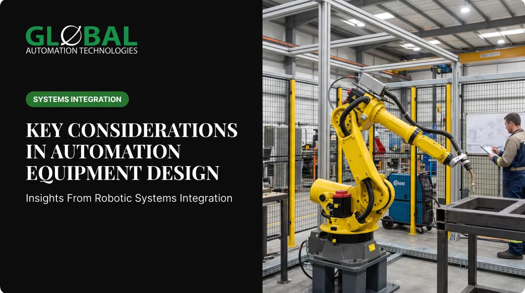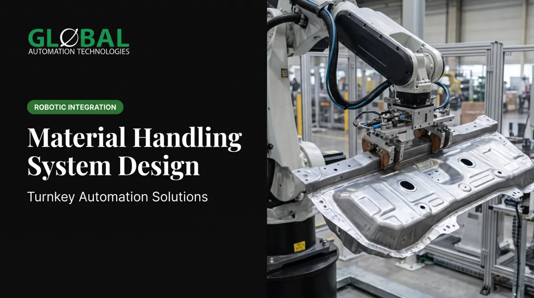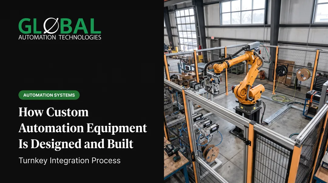

The core challenge: balancing functional requirements with manufacturability, cost constraints, safety mandates, and long-term serviceability. NIST estimated $119.1 billion in 2016 losses from preventable maintenance problems in U.S. discrete manufacturing, including $18.1 billion from downtime alone. OSHA reports approximately 18,000 serious machine-related injuries and more than 800 deaths annually from inadequately guarded or poorly designed machinery. These consequences establish equipment design as a risk-reduction and value-creation discipline, not merely a technical drawing exercise.
Key Takeaways
- Turn functional requirements into reliable, manufacturable systems with safety, cost, and compliance built in from day one
- Unite mechanical, materials, controls, manufacturing, and human factors into one production-ready design
- Validate concepts with CAD, FEA, simulation, and rapid prototyping before physical builds
- Embed safety, maintainability, and lifecycle economics early—never retrofit after production
What Is Engineering Equipment Design?
Engineering equipment design is the systematic process of creating mechanical devices and systems that perform specific industrial functions under defined operating conditions. ABET defines engineering design as "a process of devising a system, component, or process to meet desired needs and specifications within constraints."
For industrial equipment, those constraints include structural loads, environmental exposure, production volumes, regulatory compliance, budget limits, and operator interaction.
Equipment design differs from consumer product design:
- Emphasis on durability and reliability over extended lifecycles in harsh environments
- Integration with manufacturing processes, conveyor systems, control networks, and existing plant infrastructure
- Operator interaction focused on safety, accessibility, and maintenance rather than aesthetics
- Compliance with workplace safety regulations (OSHA 29 CFR 1910.212, ANSI B11.0-2023, ISO 12100:2010)
Equipment design is multidisciplinary. Typical contributors include:
- Mechanical engineers for structural integrity, kinematics, material selection, and thermal management
- Electrical engineers for power distribution, motors, sensors, and controls
- Controls engineers for PLC logic, HMI interfaces, motion profiles, and safety interlocks
- Manufacturing engineers who keep fabrication, assembly, and validation inside cost and schedule limits

Scope ranges from small components to complete systems:
- Fixtures, jigs, and tooling for part presentation and positioning
- End-of-arm tooling and grippers for robotic cells
- Standalone machines (presses, conveyors, assembly stations)
- Integrated robotic cells for welding, painting, dispensing, machine tending, and material handling
- Complete production lines with coordinated motion, part tracking, and real-time quality verification
Core Principles of Engineering Equipment Design
Strong equipment design rests on a few non-negotiable principles. Each one shapes how production machinery, robotic cells, and custom automation hold up on the plant floor.
Functionality and Reliability
Equipment must reliably perform its intended task under specified operating conditions throughout its design life. IEC dependability standards set out requirements for availability, reliability, maintainability, and failure-mode analysis during design.
Define performance metrics first (cycle time, throughput, accuracy, repeatability), then engineer components and systems to hit those targets consistently.
Structural Integrity and Stress Analysis
Components must withstand applied loads, vibrations, thermal expansion, and fatigue over the equipment's lifecycle. ASME V&V 10 (2019, reaffirmed 2025) provides a framework for verification, validation, and uncertainty quantification of computational solid-mechanics models.
Finite element analysis (FEA) predicts stress concentrations, deflections, and failure modes, but digital results still need physical validation against real-world operating conditions. NIST treats fatigue and fracture as material-reliability problems that require property data, predictive models, and measurement science.
Manufacturability
Designing equipment that can be produced efficiently with available processes and cost constraints prevents costly redesigns. NIST's 1994 design-for-manufacturing (DFM) research stressed integrating manufacturability critique into CAD workflows instead of waiting until design release.
Practical DFM moves include:
- Simplifying geometries
- Minimizing part counts
- Using standard components
- Specifying achievable tolerances
- Considering assembly sequences during initial design

Safety by Design
ISO 12100:2010 supplies machinery risk-assessment and risk-reduction principles for designers. ANSI B11.0-2023 applies those principles to new, existing, modified, and rebuilt power-driven machines. Safety belongs in the design from day one, not as a retrofit.
This includes:
- Eliminating hazards through inherently safe design (removing pinch points, limiting forces, reducing speeds in danger zones)
- Incorporating guards for points of operation, rotating parts, and ingoing nip points (OSHA 29 CFR 1910.212)
- Installing emergency stops, interlocks, and fail-safe mechanisms
- Documenting residual risks and providing training, warnings, and procedures
Maintainability
Equipment must allow safe, efficient access to wear parts, adjustments, and diagnostic points. IEC 60706-2 addresses maintainability requirements during design; IEC 60300-3-10:2025 covers maintainability and maintenance integration.
Design for service with:
- Tool-less access where practical
- Modular subsystems for quick replacement
- Diagnostic connectivity for predictive maintenance
- Clear labeling of service points
The Engineering Equipment Design Process
1. Requirements Definition
Gather specifications for loads, speeds, environmental conditions, production volumes, budget, and regulatory requirements. Build in maintainability and lifecycle targets early—not only day-one performance.
For a machine-tending cell, define:
- Part geometry and weight
- Target cycle time
- Machine-interface signals
- Floor-space limits and safety-zone boundaries
NIST research on manufacturing machinery maintenance found that plants using less than 50% reactive maintenance, with stronger predictive-maintenance adoption, saw 15% less downtime, 87% fewer defects, and 66% lower inventory increases. Those outcomes start with requirements that treat uptime and service access as design inputs.
2. Conceptual Design
Generate multiple design concepts through sketching, brainstorming, and preliminary feasibility analysis. Evaluate alternatives against requirements, constraints, and risk factors. Identify preferred approaches based on performance potential, cost, complexity, and schedule.
3. Detailed Engineering
Create precise CAD models with dimensions, tolerances, material specifications, and assembly relationships. Document electrical schematics, control architecture, and pneumatic or hydraulic circuits.
Teams designing robotic systems often use AI-assisted simulation to model, test, and optimize programs before deployment. That work can cut programming time from weeks to days and surface issues before commissioning.
4. Analysis and Simulation
Run the analyses that match the risk profile:
- Finite element analysis (FEA) for stress and deflection
- Kinematic simulation for motion paths and interference
- Thermal analysis for heat-sensitive components
- Dynamic analysis for vibration
NIST reports that model-based product-definition pilots shortened design-to-manufacturing cycle time and improved final-part quality. Virtual validation cuts physical prototype loops and reduces risk in production launches.
5. Prototyping and Testing
Build physical prototypes or subsystems to verify performance, catch assembly issues, and test assumptions from the digital design. Physical trials expose friction, clearances, operator interaction problems, and environmental effects that simulation often misses.
Virtual machining and cell tests still help: they flag path errors and wasted motion before metal is cut or a robot hits the floor. Use them to narrow what must be proven on hardware—not to skip hardware entirely.
6. Design Refinement and Documentation
Iterate based on test results, finalize engineering drawings, create bills of materials (BOMs), and prepare manufacturing and assembly documentation. Include risk assessments, validation records, operator manuals, maintenance procedures, and change-control processes to support production, commissioning, and lifecycle support.

Key Considerations in Equipment Design
Material Selection
Select materials based on:
- Mechanical properties (tensile strength, yield strength, hardness, toughness)
- Environmental conditions (corrosion resistance, temperature limits, chemical exposure)
- Weight constraints and fatigue resistance
- Manufacturing process compatibility (machinability, weldability, formability)
- Availability and cost-effectiveness
Rank candidates against the full duty cycle—peak load, cyclic stress, and process exposure—not a single property in isolation. ASM materials handbooks remain a solid reference when you need published property data to back that comparison.
Operating Environment
Material choice only holds up if the design also matches the conditions on the plant floor. Industrial equipment often faces:
- Temperature extremes (process heat, outdoor exposure, refrigerated environments)
- Dust, debris, and liquid intrusion (NEMA enclosure ratings, IEC 60529 IP ratings)
- Humidity, chemical exposure, and wash-down requirements
- Vibration, shock, and electromagnetic interference
Specify enclosures, seals, coatings, and finishes for the harshest condition the equipment will see—not the average day. Use NEMA and IEC IP ratings to lock those protections into the spec.
Human Factors and Ergonomics
Protection from the environment still leaves the operator in the loop. ISO 6385:2016 sets ergonomic principles for work-system design, and NIOSH flags lifting, awkward postures, vibration, cold, and high-intensity or high-frequency tasks as musculoskeletal risk factors.
Design controls, interfaces, and maintenance access around what operators can safely do:
- Position controls within comfortable reach zones
- Minimize repetitive lifting and awkward postures
- Provide clear sightlines for operation and inspection
- Design for safe maintenance access without disassembly of major components
- Integrate lockout/tagout capability for service and repair
Design Tools and Technologies
Computer-Aided Design (CAD) Software
Create detailed 3D models and 2D manufacturing drawings. Industry platforms include:
- SOLIDWORKS – Parts, assemblies, drawings, sheet-metal and framing tools, cloud collaboration
- AutoCAD Mechanical – Standards-based content, automated BOM workflows, 700,000+ intelligent parts and features
- CATIA – Concept through validation and lifecycle management, with system-level discipline integration
Parametric modeling allows rapid design changes. Assembly management ensures parts fit and move correctly.
Simulation and Analysis Tools
Predict real-world performance before manufacturing:
- Ansys Mechanical – Linear dynamics and multi-part contact analysis for structural validation
- Abaqus – FEA for large deformation, complex contact, and nonlinear materials
- CAD/CAM simulation – Virtual machining tests identify toolpath errors and material waste before cutting (Autodesk, Siemens NX)
Simulations cut physical prototyping cycles and lower development costs before metal is cut.

Rapid Prototyping Technologies
Enable quick iteration and physical validation:
- 3D printing (additive manufacturing) – Fast builds for customized parts; NIST notes consistency and QA can still be difficult and costly
- CNC machining – Accurate, repeatable production of prototype components from production-intent materials
- Hybrid approaches – Combine additive methods for complex geometries with subtractive finishing for precision surfaces
Best Practices for Successful Equipment Design
Design for Manufacturing (DFM)
Integrate manufacturability into the design process:
- Simplify component geometries to reduce machining time and cost
- Minimize part count through consolidation and multifunctional designs
- Use standard fasteners, motors, bearings, and components where possible
- Specify achievable tolerances that match process capabilities
- Design for assembly sequence: parts should go together without special tooling or awkward fixturing
NIST's DFM research supports integrating manufacturing critique while geometry is still editable in CAD.
Manufacturable geometry only holds if the right disciplines shape it together.
Multidisciplinary Collaboration
Bring mechanical, electrical, controls, and manufacturing engineering into the project early, not only at installation. ASME stresses that advanced machine engineering works when these capabilities share one collaborative environment so equipment can be designed, built, and commissioned cost-effectively.
NIST defines concurrent engineering as integrating people, systems, and information so knowledge is captured and exchanged while decisions are still cheap to change. Teams that work this way typically:
- Catch mechanical–controls interface issues before hardware is ordered
- Align robot reach, tooling, and safety layout in the same design pass
- Cut commissioning rework and late change orders on the plant floor
Cross-functional design also sets up lower cost over the full service life of the cell.
Lifecycle Thinking
Consider total cost of ownership, not just initial capital:
- Energy consumption during operation
- Maintenance requirements and access for service
- Spare-parts availability and replacement intervals
- Eventual decommissioning and disposal
NIST's lifecycle-cost analysis (LCCA) framework evaluates ownership, operation, maintenance, and disposal costs. Designing for lower energy use, easier maintenance, and longer component life reduces operating expenses and downtime over the equipment's service life.
Frequently Asked Questions
What are the four C's of engineering design?
The "Four C's" is not a standardized framework in ANSI, ISO, ASME, or ABET. Education literature often cites Creativity, Complexity, Choice, and Compromise, or Customer requirements, Creativity, Communication, and Constraints, as design principles.
What are the 8 steps of engineering design?
A common educational model runs: define the problem, research, specify requirements, brainstorm, choose a solution, develop it, prototype, then test and redesign. Industrial practice also adds documentation, risk assessment, validation records, and change control.
What is the difference between equipment design and machine design?
The terms are often used interchangeably. Machine design usually means a single power-driven machine; equipment design covers broader systems, including machines, fixtures, guarding, controls, material handling, utilities, and line integration. This article uses the broader scope.
What software tools do engineers use for equipment design?
Engineers typically use CAD for 3D modeling and drafting (SOLIDWORKS, AutoCAD, CATIA) and FEA for stress and thermal analysis (ANSYS, Abaqus). Teams also rely on motion and process simulation, CAM for manufacturing prep, and PDM/PLM for documentation and change control.
How do safety standards influence equipment design?
Standards such as OSHA 29 CFR 1910.212, ANSI B11.0-2023, ISO 12100:2010, and EU CE marking set requirements for guarding, e-stops, lockout/tagout, and risk assessment. They must shape layout, motion limits, interlocks, and operator access from the start.
What role does prototyping play in equipment design?
Virtual and physical prototypes validate designs, surface assembly and operational issues, and support user feedback before full-scale build. That reduces commissioning surprises and speeds production readiness.